| Model | Cavity | Max Feed size(mm) | Min feed Discharge size(mm) | Power (kw) | Capacity(t/h) in different discharge size(mm) | |||||||||
| 6 | 10 | 13 | 16 | 19 | 22 | 25 | 38 | 61 | 64 | |||||
| 6 | 10 | 13 | 16 | 19 | 22 | 25 | 38 | 51 | 64 | |||||
| GPH600 | C | 95 | 10 | 55 | 20 | 25 | 30 | 35 | 45 | 50 | 76 | |||
| M | 72 | 6 | 55 | 18 | 20 | 25 | 30 | 35 | 45 | 45 | 60 | |||
| GPH1000 | C | 160 | 13 | 110 | 70 | 90 | 125 | 135 | 160 | 215 | ||||
| M | 115 | 10 | 110 | 55 | 65 | 70 | 90 | 120 | 135 | |||||
| F | 80 | 8 | 110 | 47 | 50 | 60 | 67 | 90 | ||||||
| GPH1200 | C | 180 | 13 | 132 | 105 | 120 | 135 | 160 | 180 | 220 | ||||
| M | 130 | 10 | 132 | 72 | 92 | 105 | 135 | 150 | 170 | |||||
| F | 90 | 10 | 132 | 70 | 90 | 100 | 125 | |||||||
| GPH1300 | C | 200 | 16 | 160 | 135 | 160 | 180 | 200 | 290 | 350 | ||||
| M | 150 | 13 | 160 | 105 | 125 | 135 | 160 | 180 | ||||||
| F | 102 | 10 | 160 | 80 | 105 | 135 | 140 | |||||||
| GPH1400 | C | 215 | 19 | 200 | 200 | 220 | 270 | 350 | 440 | |||||
| M | 160 | 16 | 200 | 160 | 180 | 200 | 230 | |||||||
| F | 115 | 13 | 200 | 150 | 195 | 220 | 240 | |||||||
| GPH1500 | C | 235 | 22 | 220-250 | 230 | 265 | 330 | 450 | 420 | 570 | ||||
| M | 175 | 19 | 220-250 | 215 | 240 | 270 | 330 | |||||||
| F | 130 | 13 | 220-250 | 180 | 210 | 240 | 265 | 285 | ||||||
| GPH1650 | C | 267 | 22 | 250-300 | 330 | 390 | 500 | 650 | 725 | |||||
| M | 203 | 16 | 250-300 | 240 | 250 | 280 | 330 | |||||||
| F | 140 | 13 | 250-300 | 190 | 220 | 260 | 330 | |||||||
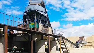
1.A defined role in the crushing circuit
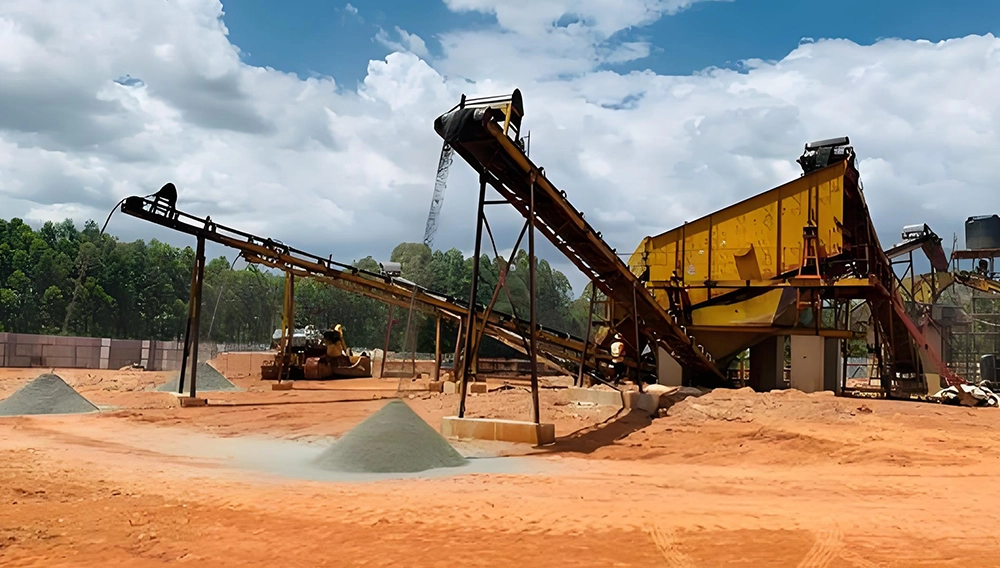
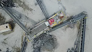
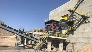
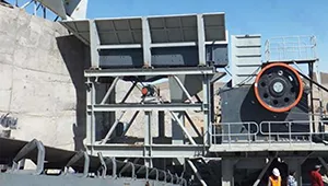
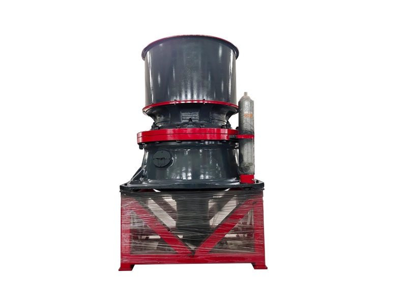
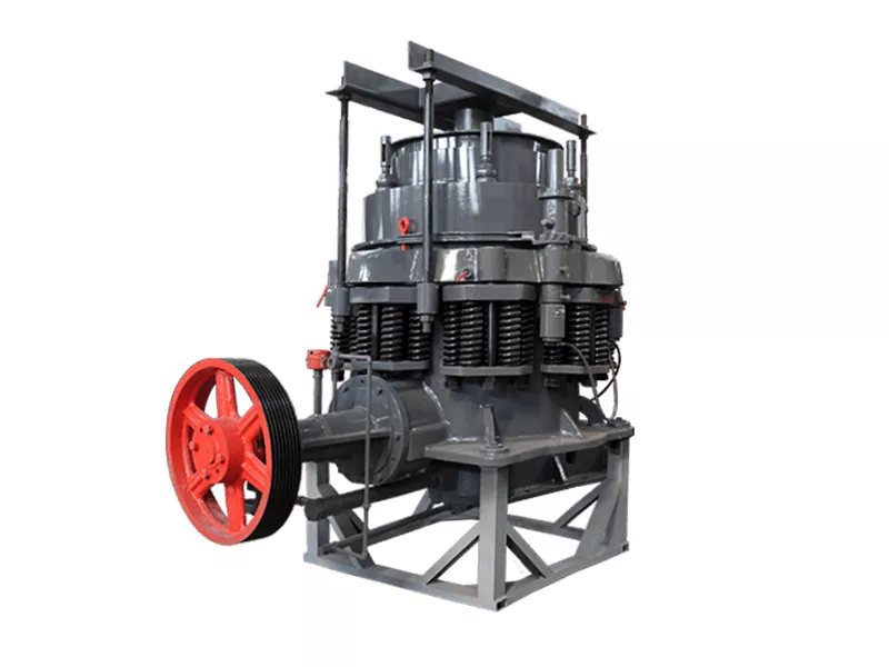
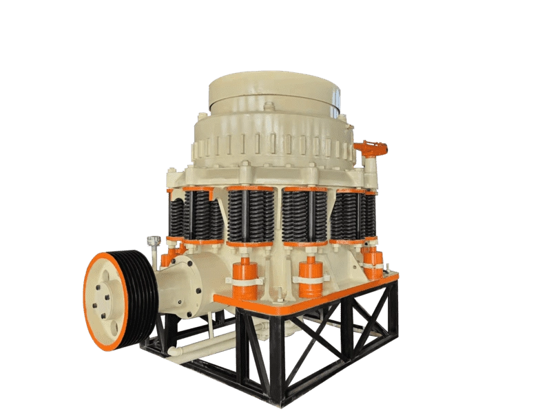
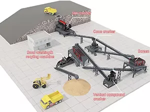
A GPH compound cone crusher reduces prepared feed in the secondary or fine-crushing stage. Specify the incoming material and the required screening products when reviewing its position in the plant. Coordinate the feed and discharge conveyors with the proposed crusher duty.
2.Select by model and chamber
Technical Data lists GPH model groups with C, M and F cavity options where available, and shows capacity across discharge settings. Read the complete row for the proposed combination rather than combining values from different chambers. Review feed size, setting, capacity and motor power together.
3.Feed, setting and throughput
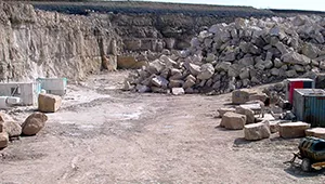
Record the feed grading, material strength, abrasiveness and moisture, along with the required throughput and product sizes. These conditions, the operating setting and liner condition affect performance. Confirm the selection for the actual duty and the intended screening circuit.
4.Lubrication and wear checks
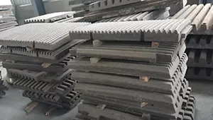
Inspect the supplied lubrication and sealing arrangement, chamber liners and drive components in accordance with the machine manual. Allow space for inspection, lifting and replacement work. Plan parts identification and maintenance around the specific assembly and operating conditions.
5.Confirm the supplied configuration
Before ordering, agree the selected chamber, drive and electrical supply, support arrangement, installation interfaces and service scope. For spare parts, use the machine identification and component drawings to check compatibility. Confirm the required control and protection functions for the offered configuration.



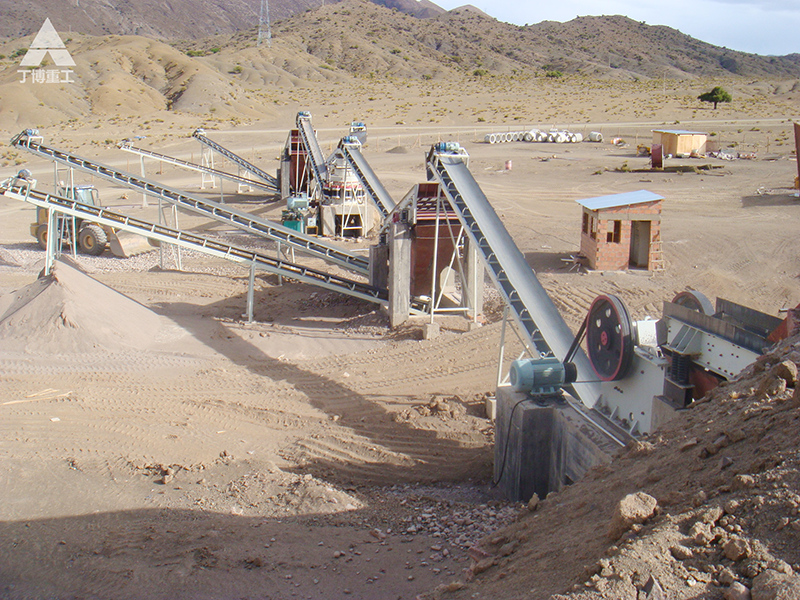
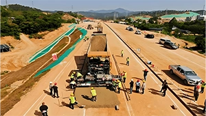
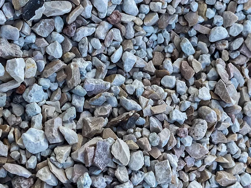
|
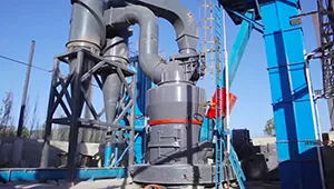
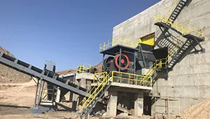
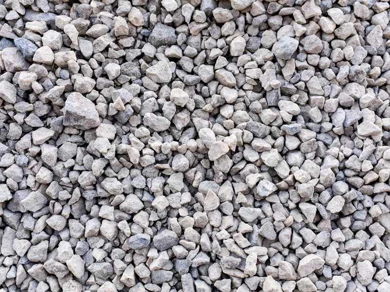
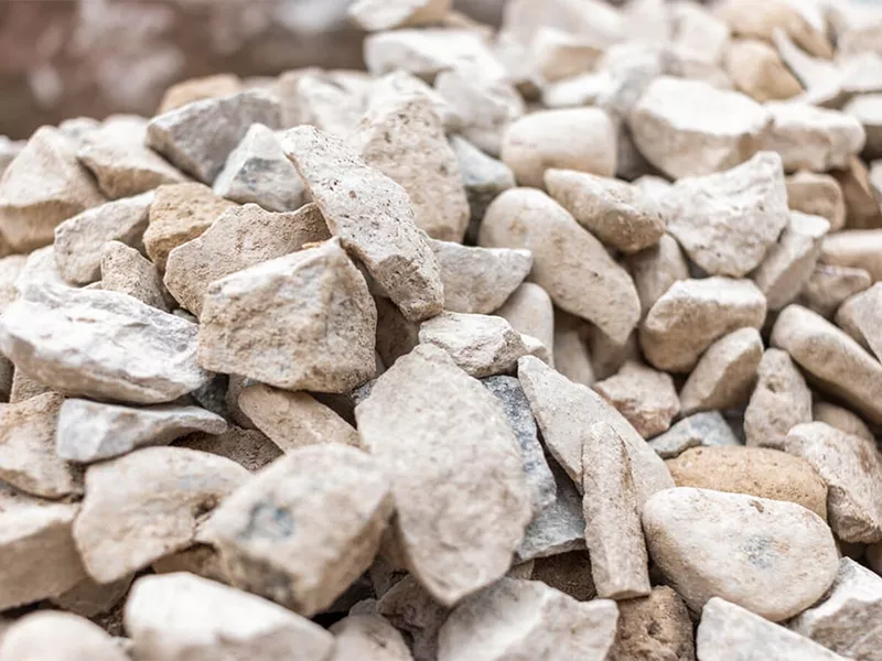
Tonnage
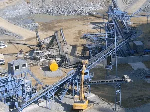
500T/H
|
Material
Limestone
|
|
Output
0-5mm 5-10mm 10-20mm 20-40mm
|
End Use
Building materials, chemical industry, road construction and so on.
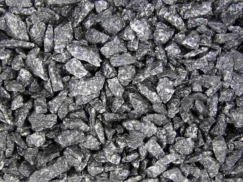
|
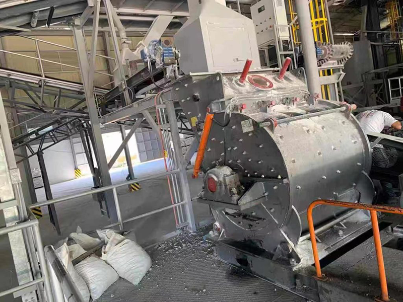
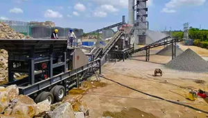
|
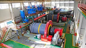
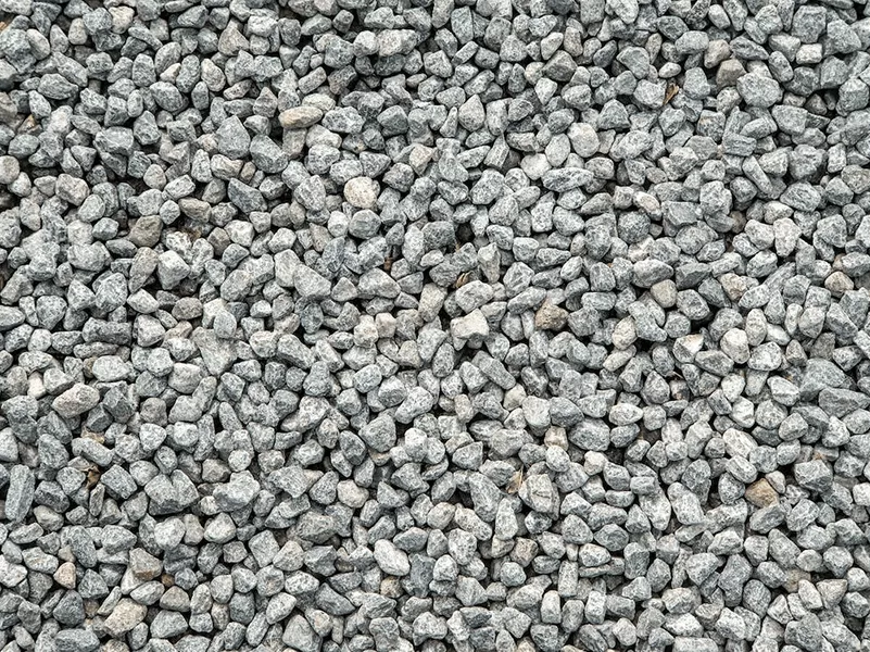
Tonnage
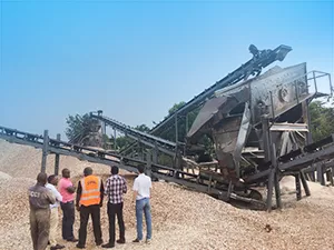
15T/H
|
Material
Granite
|
|
Output
0-1mm 1-1.5mm 1.5-2mm 2-3mm
|
End Use
For the use of his company's paint processing base.
|